Thermal Spray Coating

Metallographic preparation of thermal spray coatings

Thermal spray coatings are widely used across many applications – but they can be difficult to prepare for metallographic investigation. What are the main challenges when preparing thermal spray coatings and how can you overcome them?

Download the full application note

The main characteristics of thermal spray coatings

Thermal spray coatings are applied to a substrate to give it a specific surface quality that it would not otherwise have. Thus, the substrate is responsible for the bulk strength of a part; the coating adds superior surface qualities, such as corrosion, wear or heat resistance.

Thermal spraying was invented in the early 1900s using zinc to ‘metallize’ substrates for corrosion protection. Today, a multitude of different spray materials are used – such as ceramics, carbides, composites and metals – and thermal spray coatings are widely used in the aerospace and power generation industry for new and refurbished sections and parts.

Metallography of thermal spray coatings

Metallography of thermal spray coatings can have several purposes: to define, monitor and control spraying conditions for quality control; for failure analysis; and during development of new products. The procedure normally involves coating a test coupon to define and optimize the process for the part to be sprayed. Sections of this test coupon are then metallographically prepared and examined to assess:
  • Coating thickness
  • Size and distribution of porosity
  • Oxides and cracks
  • Adhesion to base material
  • Interface contamination
  • Presence of unmelted particles
There are many different coating materials, sometimes with unusual combinations. Therefore, it is important to know what coating and substrate material you are preparing for analysis, as this will enable you to estimate how the materials will behave under mechanical abrasion. As different spraying processes result in different coating densities and structures, it also helps to know the spraying method used on a particular sample in order to estimate the porosity and oxide content.

Difficulties in the preparation of thermal spray coatings

How to estimate the true porosity in a metallographically prepared spray coating is still up for debate, as metallographic grinding and polishing, if not carried out correctly, can introduce artefacts which are not part of the coating structure.

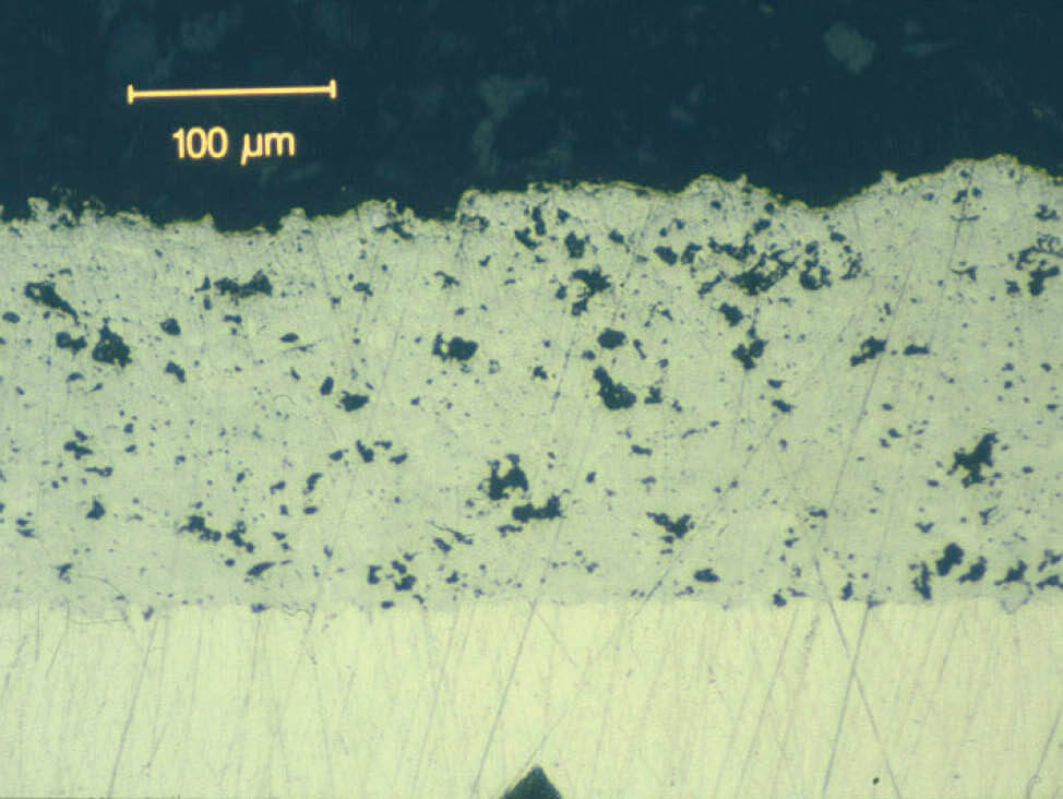
For example, in metal or metal/ceramic coatings, the softer metal is smeared into pores during grinding and, if not polished properly, can cover up the true porosity. In comparison, ceramic coatings are brittle and particles break out of the surface during grinding. If not polished thoroughly, these particles leave an incorrect impression of high porosity.

In general, common difficulties with preparing thermal spray coatings for metallographic analysis include:

Cutting: Clamping of spray coated workpieces for sectioning can introduce cracks in brittle coatings or compress very soft coatings.

Mounting: Cold mounting resins with high shrinkage can cause damage to coatings with weak adhesion to the substrate; due to the shrinkage gap, the coating is not supported by resin, which can lead to delamination of the coating during grinding and polishing.

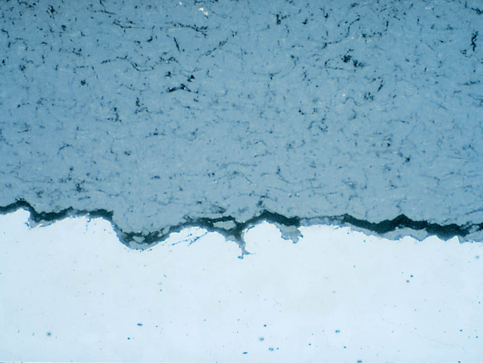
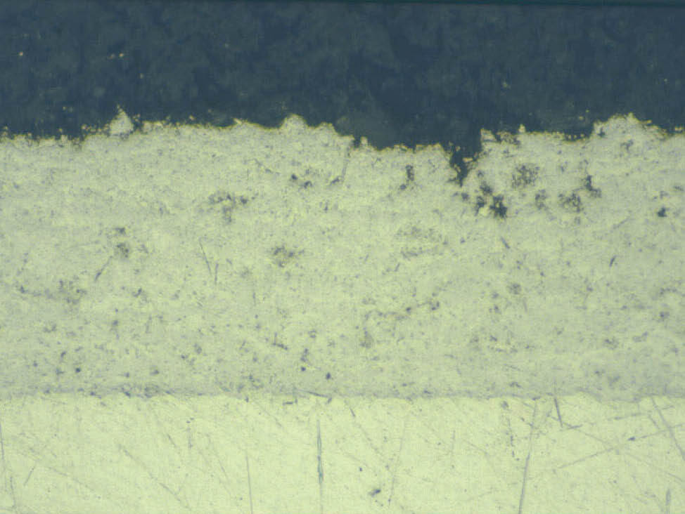
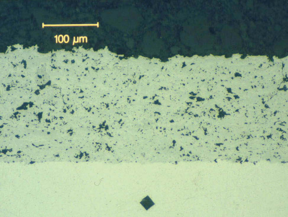
Grinding and polishing: Edge-rounding can lead to uneven polishing and subsequent misinterpretation of the coating density. In addition, relief between coating and substrate creates a shadow that can be misinterpreted.
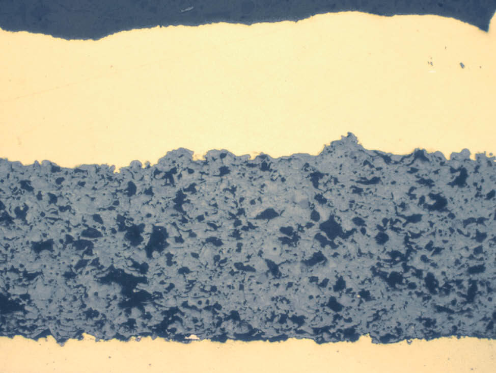
Thermal Spray Coatings
Fig. 1: Ceramic spray coating, insufficiently polished
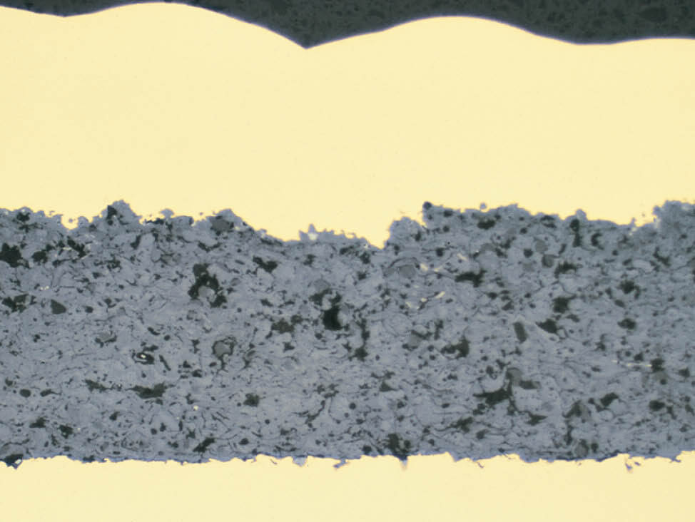
Thermal Spray Coatings
Fig. 2: Same coating as figure 1, but polished correctly
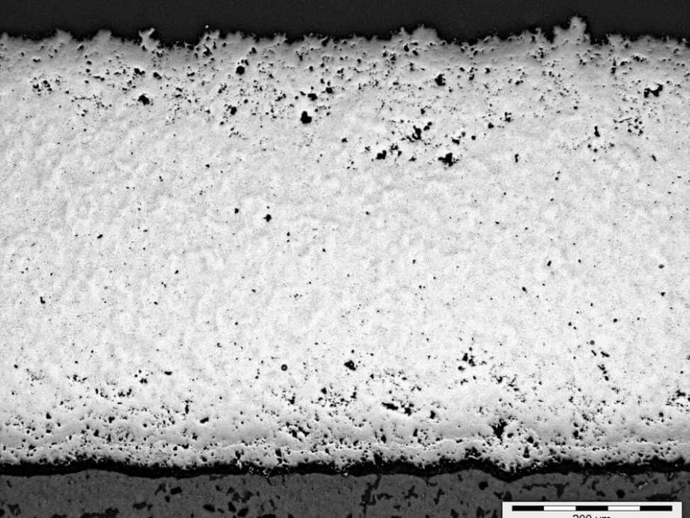
Thermal Spray Coatings
Fig. 3: Edge-rounding can lead to uneven polishing and subsequent misinterpretation of coating density – in this case an incorrect polish suggests less porosity in the middle of the coating
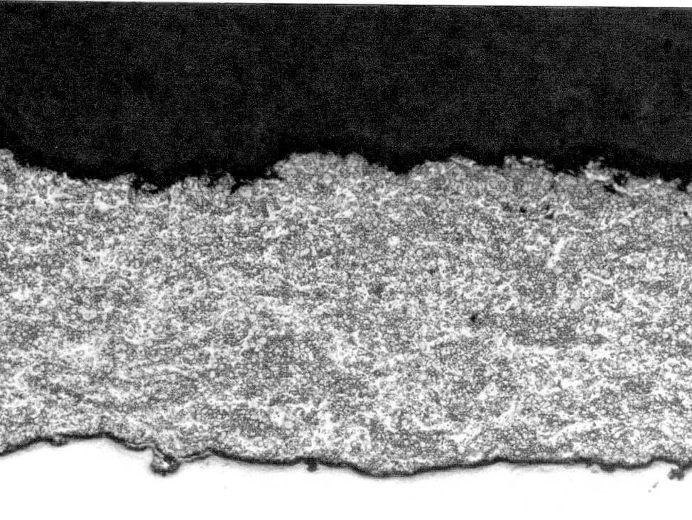
Thermal Spray Coatings
Fig. 4: Relief between coating and substrate creates a shadow that can be misinterpreted – in this case, a WC/Co spray coating with relief polish shows a dark line at resin/coating interface


Preparation of thermal spray coatings: Cutting & mounting

Cutting thermal spray coatings

When selecting a cut-off wheel, the main consideration is the substrate material (which is usually metallic). However, to avoid dragging brittle particles from the coating, select a wheel with a loose bond (soft), particularly when cutting parts with ceramic coatings. Even if the coat¬ing is ceramic, it constitutes only a small percentage of the total cross section¬al area and does not need to be cut with a diamond cut-off wheel. Usually sectioning is possible with a soft aluminum oxide wheel. If the ceramic coating is very thick, a dense resin-bonded diamond cut-off wheel can be used as an alternative.

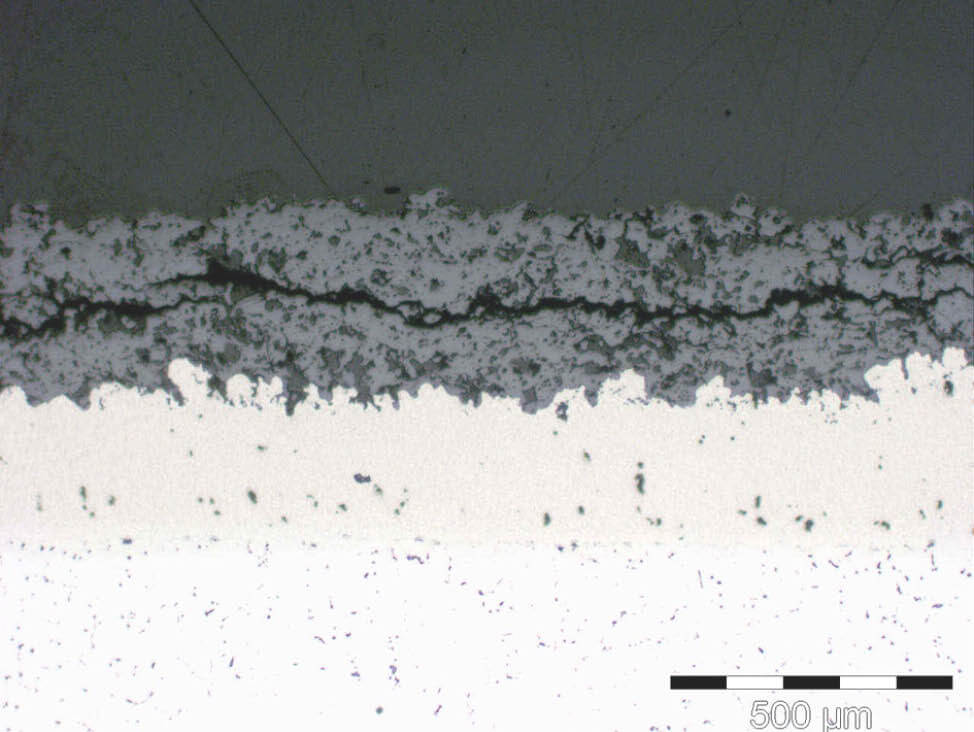
It is possible that cracks caused by cutting may appear in the coating after final polishing. If this is the case, re-grind and polish the sample. If the crack is from cutting, it will usually disappear. If the crack is not the result of cutting, it will re-appear or cracks may appear in other areas.

Tip: How to protect brittle and very soft coatings
A thin piece of Styrofoam or rubber between the clamps and sample can help to protect brittle and very soft coatings from being damaged.

Tip: How to avoid delamination
When cutting pieces other than test coupons, cut into the coating towards the substrate, not from the substrate into the coating, as this will help avoid drag from the cut-off wheel causing the coating bond to delaminate from the substrate.

Tip: How to protect fragile coatings
Vacuum impregnate with cold mounting epoxy resin before cutting to protect fragile or thin coatings during sectioning. The cut pieces can then be remounted prior to grinding and polishing.

Thermal Spray Coatings
Fig. 5: Crack between a plasma spray coating and the substrate, resulting from cutting 

Thermal Spray Coatings
Fig. 6: Cracks introduced through sectioning

Mounting thermal spray coatings

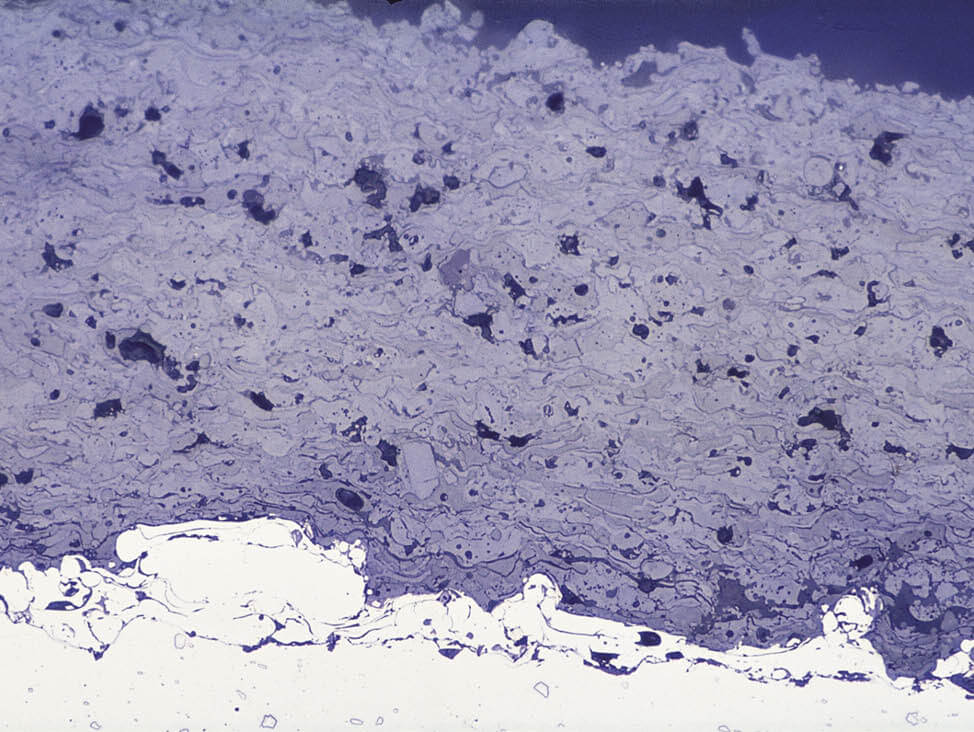
Hot compression mounting is not recommended, as this easily damages spray coatings. Instead, we recommend cold mounting with epoxy resin (ProntoFix, EpoFix, CaldoFix-2). However, please note that cold mounting resins with high shrinkage can cause damage to coatings with weak adhesion to the substrate.

In general, vacuum impregnation is recommended for all coatings. The depth of impregnation depends on the degree of porosity and interconnections between pores. Very porous coatings can be more easily impregnated than denser ones, while coatings with less than 10 % porosity cannot be impregnated successfully.

Tip: How to distinguish voids
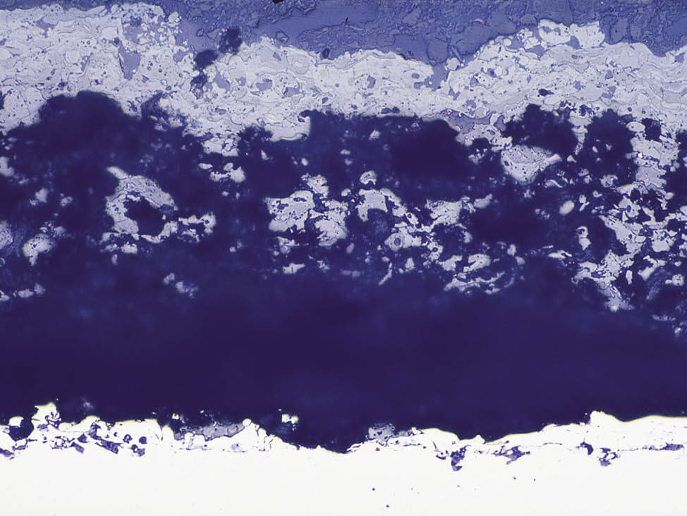
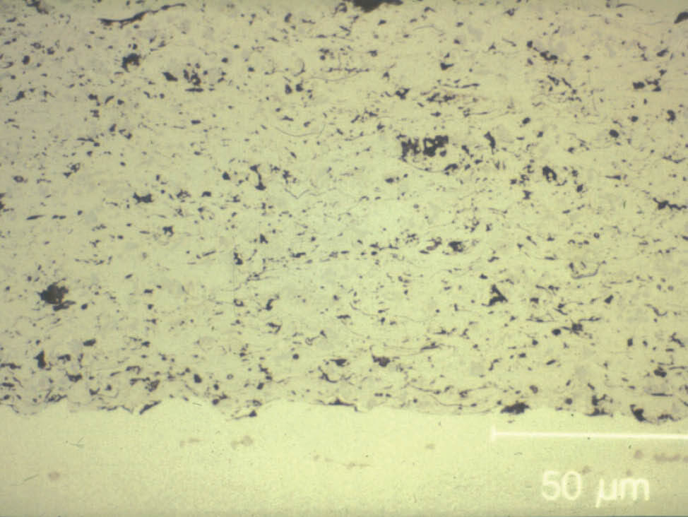
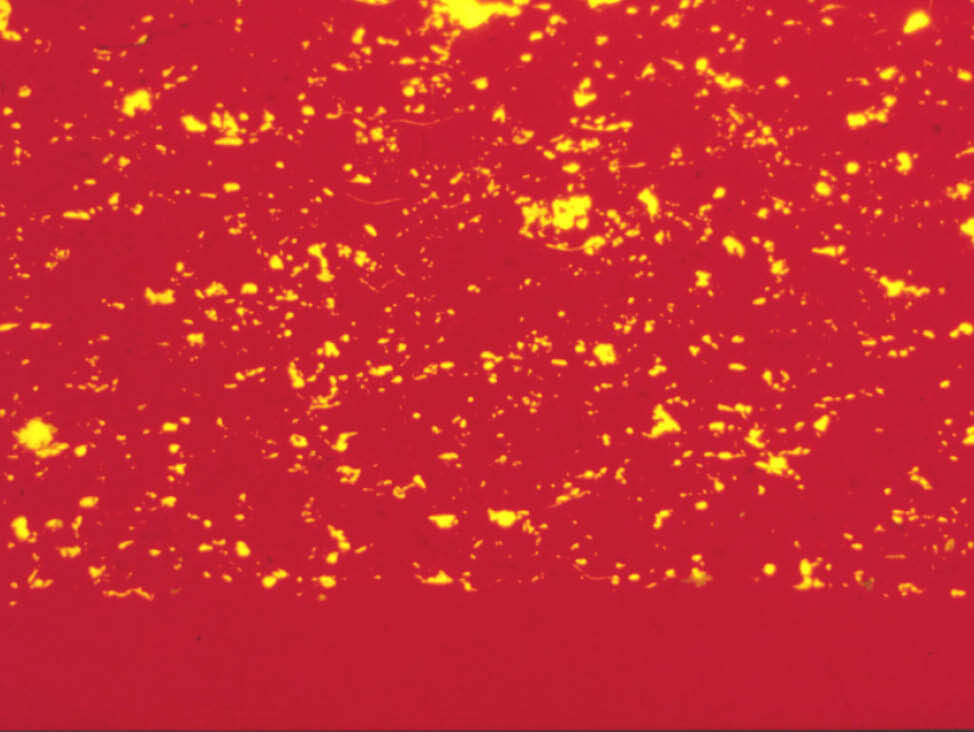
It can be difficult to distinguish voids filled with transparent or translucent mounting resins from the structural elements of the coating. The solution is to mix a fluorescent dye (Epodye) into the cold mounting resin. This will color the voids yellow when using a long pass blue filter and a short pass orange filter. (This technique doesn’t work on ceramic coatings, as these are translucent and the whole coating appears fluorescent.)

Thermal Spray Coatings
Fig. 7: Damage to a ceramic spray coating due to hot compression mounting

Thermal Spray Coatings
Fig. 8: Same coating as figure 9, cold mounted

Thermal Spray Coatings
Fig. 9: WC/Co plasma spray coating in brightfield

Thermal Spray Coatings
Fig. 10: Same coating as in figure 11, in fluorescent light


Find out more

Preparation of thermal spray coatings: Grinding & polishing

Plane grinding

As a general rule, plane grinding should start with the finest possible silicon carbide foil/paper. This prevents the creation of artificial porosity by fracturing brittle particles.

However, there are exceptions:
  • Very dense or thick ceramic coatings are plane ground more effectively with diamond (e.g. MD-Piano 220, MD-Mezzo 220 or MD-Molto 220)
  • High sample volumes or large parts that need to be examined as a whole, may be plane ground with stone, as this is faster
Whichever method is used, the first preparation step is to remove any cracks caused by cutting, without introducing new damage from coarse plane grinding. When testing for the optimal preparation method, try both silicon carbide and diamond grinding to see which is the most suitable in that specific case.

Fine grinding

Fine grinding is preferably done with diamond on a composite fine grinding disc. This will retain flatness, while also giving you a good material removal rate.
  • For ceramic coatings: use the fine grinding disc MD-Allegro
  • For metal coatings: use the fine grinding disc MD-Largo

Polishing

To remove smeared metal, thoroughly polish the sample with a silk cloth (MD-Dur or MD-DAC).

Final polishing

Metal coatings can be fine polished with either 1 μm diamond or a colloidal silica (OP-U NonDry) on a soft cloth. Fumed silica suspension OP-S NonDry is not recommended for polishing metal spray coatings as it creates too much relief. However, OP-S NonDry is suitable for final polishing of ceramic coatings as it gives a good contrast to the structure.

When testing for the optimal preparation method, try both silicon carbide and diamond. In some cases, 1 µm diamond may be preferable to colloidal silica.

Thermal Spray Coatings

Thermal Spray Coatings

Find out more

Example 1: Metal spray coating

Thermal Spray Coatings
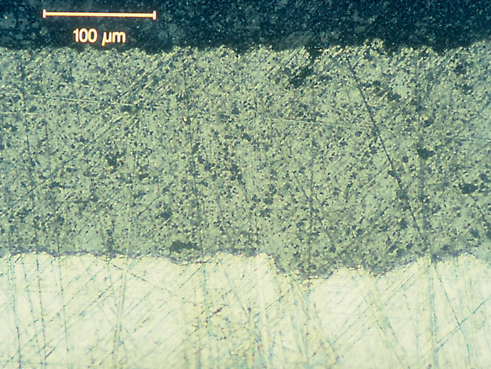
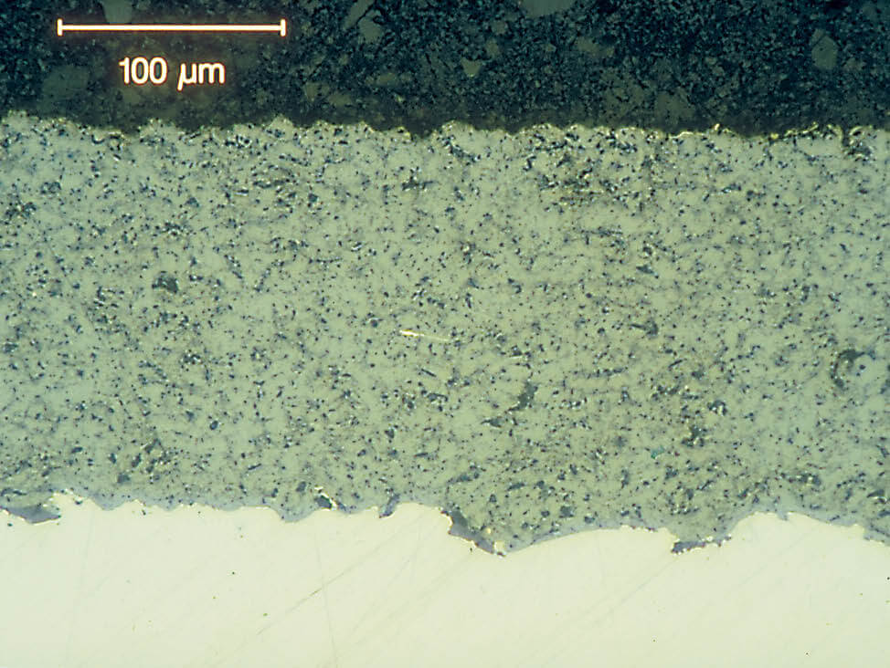
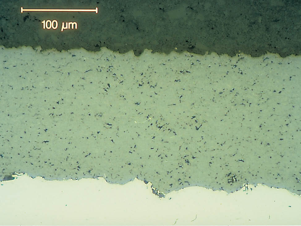
Fig. 11: Example 1: Metal spray coating. After fine grinding 

Thermal Spray Coatings
Fig. 12: Example 1: Metal spray coating. Polished with 3 µm

Thermal Spray Coatings
Fig. 13: Example 1: Metal spray coating. After final polish

Example 2: Ceramic spray coating

Thermal Spray Coatings
Fig. 14: Example 2: Ceramic spray coating. After fine grinding

Thermal Spray Coatings
Fig. 15: Example 2: Ceramic spray coating. Polished with 3 µm

Thermal Spray Coatings
Fig. 16: Example 2: Ceramic spray coating. After final polish

Etching of thermal spray coatings

Etching is not often used on thermal spray coatings as the main structure can be seen after final polishing. However, if the metallic structure must be investigated further, etching may be necessary.

As a general rule, the etchants recommended for a specific material can also be used for spray coatings made of the same material. Usually, the etching attack will be more even if the substrate is similar to the coating material.

Coatings sprayed in a controlled atmosphere have few or no oxides, which makes it difficult to recognize the coating structure. Therefore, these coatings need to be contrasted with chemical etching.

Vacuum sprayed coatings on nickel and cobalt based superalloys can be etched with the same solutions used for the substrate, or electrolytically etched with 10 % aqueous oxalic acid.

Coatings containing molybdenum can be revealed using the following etchant:
  • 50 ml water
  • 50 ml hydrogen peroxide (3 %)
  • 50 ml ammonia
DOWNLOAD THE APPLICATION NOTE INCLUDING PREPARATION METHODS

Summary

Thermal spray coatings are widely used in a number of industries to give a specific surface quality or function to a substrate – typically to improve the substrate’s resistance to corrosion, heat or wear. Metallography is often used to estimate porosity, oxides and unmelted particles, as well as adhesion to the substrate.

Key recommendations with preparing thermal spray coatings for metallographic preparation include:
  • Incorrect grinding and polishing procedures can influence the analysis, so prepare the materials systematically to make the results reproducible.
  • It is important to use the right cut-off wheels in precision cutting to avoid cracks in the coating. This should be followed by epoxy mounting.
  • As coatings are easily damaged by coarse grinding. Therefore, grinding should be done with the finest grit possible.
  • Fine grinding should be done with diamond on a rigid disc (to avoid relief), followed by a thorough diamond polish on a silk cloth.

Get insight into other materials

Learn more about the materialography of other materials, check out our materials page.